")
15KV Boost High Voltage Generator High Frequency Transformer Inverter Arc Igniter Coil Module Disassembled Parts for DIY Use 2Sets(Include PCB Board)


Price: $7.19
(as of Mar 20, 2026 13:02:54 UTC – Details)

A Technical Deep Dive: 15KV Boost High Voltage Generator DIY Kit Review
For electronics enthusiasts and hobbyists seeking a hands-on project with a dramatic, high-voltage payoff, the “15KV Boost High Voltage Generator High Frequency Transformer Inverter Arc Igniter Coil Module Disassembled Parts for DIY Use (2 Sets, Include PCB Board)” presents a compelling, albeit challenging, proposition. This is not a toy or a plug-and-play device; it is a raw, unassembled kit designed to build a compact, high-frequency inverter circuit capable of producing a stable, high-temperature plasma arc. Based solely on the provided technical description and installation notes, this review will deconstruct the kit’s components, assembly intricacies, operational principles, and its rightful place in the DIY ecosystem.
Unpacking the Kit: Components and Design Philosophy
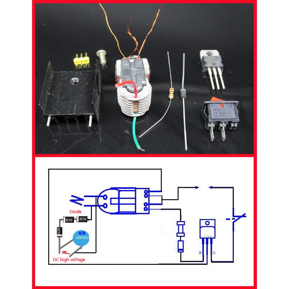
Each set is comprehensive, providing the essential discrete components mounted on or intended for a dedicated PCB. The heart of the system is the custom-designed PCB, which serves as both a wiring harness and a platform for the critical high-frequency switching circuit. Key components include:
- N20 Transistor: The workhorse switching element. This small signal NPN transistor is tasked with rapidly turning the primary transformer winding on and off at high frequency. Its inclusion of a heatsink is a non-negotiable requirement given the high current pulses it will handle.
- UF4007 Ultra-Fast Recovery Diode: This is a critical component placed across the transformer’s primary or in the feedback path. Its ultra-fast recovery time is essential in high-frequency inverters to minimize switching losses and prevent voltage spikes that could destroy the transistor.
- 120Ω Feedback Resistor (Adjustable): This resistor sets the operating point for the feedback winding. Its value is not fixed; as the description sternly warns, it must be adjusted if input voltage is increased to protect the N20 transistor from burnout.
- Boat Switch & Pin Headers: For power control and external connections.
- The Transformer: The most critical and finicky component. It is a custom-wound toroidal or cylindrical coil with two distinct primary windings (one thick, one thin) and a high-voltage secondary. The thick wire is the “main winding” (connected to the power switch and transistor), while the thin wire is the “feedback winding” (connected back to the base of the transistor via the resistor to sustain oscillation). The secondary, wound with very fine wire, generates the kilovolt-level output.
The design philosophy is one of educational transparency. By providing a disassembled transformer and a silkscreened PCB, the manufacturer forces the builder to engage with the fundamental topology of a self-oscillating Tesla coil or flyback transformer driver—a classic high-voltage novice project.
Assembly: Where Precision is Non-Negotiable
The provided “Installation Notes” are not mere suggestions; they are precise, mandatory instructions born from the physics of the circuit. The most critical step concerns the transformer lead soldering. The notes explicitly state: “thick enameled wire and fine enameled wire do not use the same side.” This refers to the two primary windings. The transformer’s primary has three connection pads. The middle pad has a large hole to accommodate both a thick and a thin enamelled wire. The rule is that these two wires must exit the pad on opposite sides—e.g., thick on the left, thin on the right, or vice versa. Soldering them to the same side would electrically short or incorrectly phase the windings, almost certainly preventing oscillation or causing immediate component failure.
Following this, the mundane but vital task of stripping enamel is highlighted. Using a blade to scrape the wire tips until shiny copper is exposed is absolutely necessary. Solder will not adhere to the insulating enamel. Any failure here guarantees a cold joint and a non-functional circuit.
The note about soldering a “3P pin at the output” is a clever mechanical fix. The high-voltage secondary output consists of two fine wires. If they are left too far apart, arcing may occur across the gap before the circuit even powers up (a “no-load” condition). Adding a third pin (likely a grounding or reference point) between them on the PCB shortens the effective electrode distance, allowing the circuit to start oscillating under load.
Operation, Tuning, and Critical Safety Protocols
Once assembled, the circuit operates from a single 3.7V Li-ion cell (18650). Its core function is to switch the main primary winding on and off at a frequency determined by the transformer’s inductance and the feedback circuit. This rapid switching induces a high-voltage pulse in the secondary. The result is a continuous, high-frequency (~tens of kHz) arc at the output terminals, hot enough to ignite paper or plastic—hence the “plasma lighter” moniker.
The path to reliable operation is a delicate tuning process:
- Initial Test: With the stock 120Ω feedback resistor and a 3.7V supply, the builder hopes for an arc. If not, the notes provide a clear, cautious protocol: if increasing input voltage (up to 12V), the feedback resistor MUST be increased proportionally (to ~150Ω – 1.5kΩ). The advice to adjust “from large to small” is key—starting too low with a high input voltage is a surefire way to smoke the N20 transistor.
- Enhancing Output: The description provides a schematic for a voltage doubler circuit (using a high-voltage capacitor and three rectifiers). Connecting this to the raw AC output rectifies and multiplies the voltage, producing a DC high voltage suitable for applications like an anion (negative ion) generator. This extensibility is a major selling point for experimenters.
- The Imperative of Potting: After successful testing, the transformer must be potted with epoxy resin or insulating wax. This is not optional. The high-voltage secondary winding, with its countless turns of fine wire, is extremely vulnerable. Vibration, moisture, or conductive dust will cause inter-winding shorts and certain failure. Potting immobilizes the windings, provides dielectric strength, and dissipates heat, transforming a fragile prototype into a durable module.
Applications and the Target User
This kit is explicitly framed for “Chinese-language general experiments, electronic instruments, negative ion generators, scientific small production.” Its primary value is as an educational tool for understanding high-frequency inverter principles, transformer coupling, and feedback oscillation. For a student or hobbyist, building this provides tangible insight into how commercial devices like ignition coils, bug zappers, or CRT flyback transformers fundamentally work.
The stated application as a component for a negative ion generator is its most practical use case. The high-voltage DC output (via the suggested doubler circuit) can corona-discharge into air, generating negative ions. Builders could integrate this into a small desktop air purifier project.
Verdict: A Specialist’s Kit with High Stakes
This is not a beginner’s kit. It is designed for the intermediate to advanced DIYer who possesses:
- Steady hands and good soldering skills (for fine-pitch work and thick wire).
- A solid conceptual understanding of transistor switches, transformers, and feedback loops.
- The patience to meticulously follow nuanced instructions (especially the transformer lead rule).
- A healthy respect for high voltage. The warning about the 15,000V maximum output (a 1.5cm arc) is serious. This voltage can cause severe painful shocks, damage electronics, and, as noted, ignite materials with ease. Proper insulation, spacing, and a safety-first mindset are mandatory.
Strengths:
- Educational Depth: Forces understanding of core high-frequency power electronics.
- Comprehensive: Includes all necessary discrete parts and PCBs for two builds.
- Extensible: Clear path to DC output for more applications.
- Transparent Design: The disassembled transformer is a key learning feature.
Challenges & Warnings:
- Assembly Precision: One misunderstood step (transformer wiring) renders the kit useless.
- Component Vulnerability: The N20 transistor is a known failure point if resistor values are wrong with high input voltage.
- Post-Assembly Process: Potting is an absolutely essential, extra step requiring additional materials (epoxy) and skill.
- Intrinsic Danger: The output is genuinely hazardous.
Conclusion
The 15KV Boost Generator DIY Kit is a niche, high-commitment product that delivers exactly what it promises: the parts and a professional schematic to build a potent high-voltage source. Its value is entirely in the building and tuning process. Success yields a functional, potenti ally dangerous piece of test equipment. Failure, often due to a skipped scraping or mis-soldered transformer lead, results in a non-working pile of components.
This kit is highly recommended only for those who deliberately seek to learn this specific circuit topology and are prepared for meticulous, careful work. It is not for the impatient or those seeking a quick gadget. For the right person—the tinkerer who loves a schematic, respects a soldering iron, and understands the gravity of a 15kV arc—this represents a fascinating and practical foray into high-voltage electronics. All others should heed the extensive warnings and perhaps seek a more forgiving first project.
")
")

")

 3 Sided Multi Plug Wall Adapter Power Strip for Home Travel Office 2 Pack")
 – Black")
